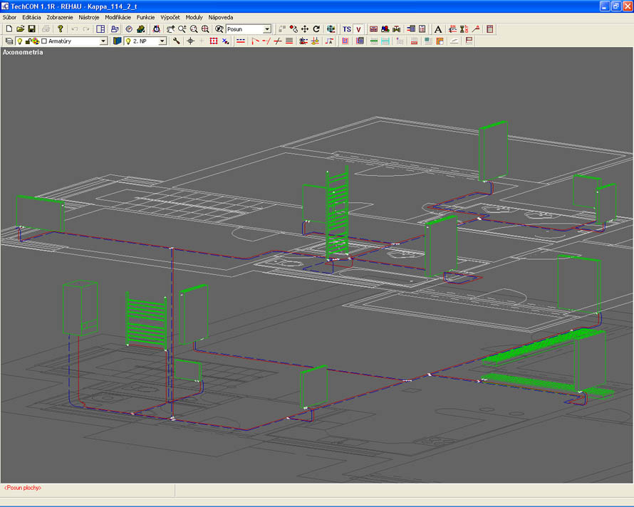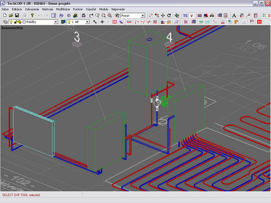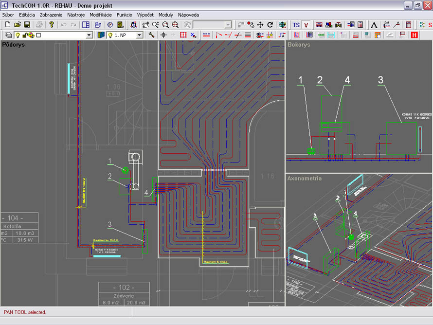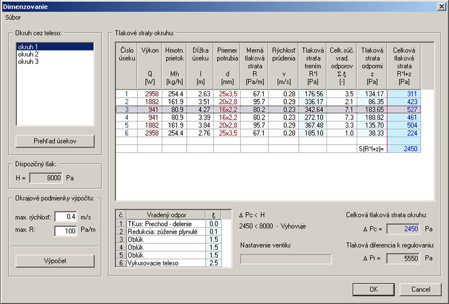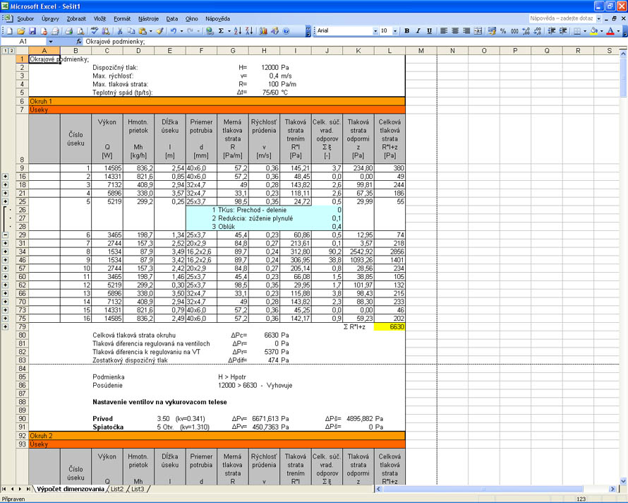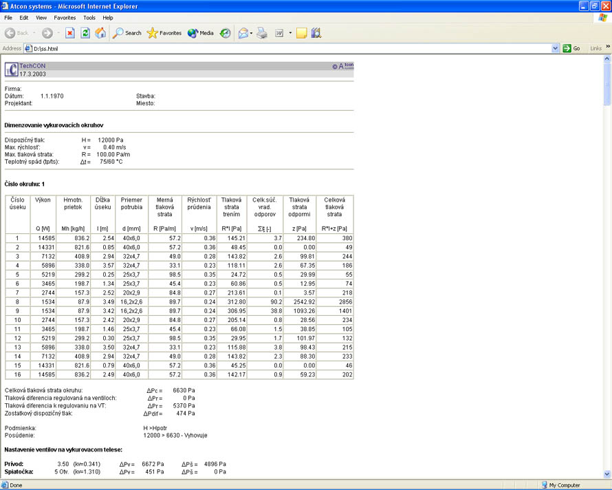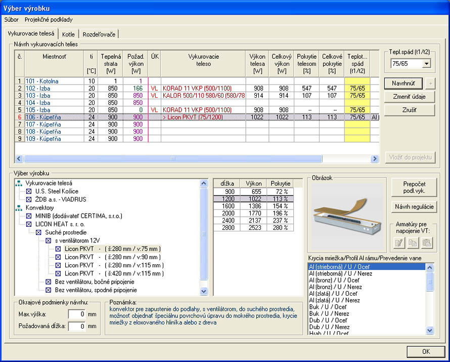
(EN) The program allows the designer to draw simultaneously in 2D and 3D views, which increases the clarity of the design process and enables free, unrestricted work during the design phase. Based on the results of heat loss calculations, the program proposes the boiler and heating units according to the designer's requirements. The individual components of the heating system (valves, dampers, distributors, EN, etc.) are selected by the designer from catalogs and inserted directly into the project as 3D objects. These objects contain all the necessary information for calculations and element listings. When entering pipe layouts, the user draws a line, but the program automatically generates 3D piping in the shape of a cylinder. The program checks the placement of pipes within the project and immediately alerts the designer in case of any collisions. Final sizing with pressure loss assessment is performed at the end. In the calculation, the program proposes pipe dimensions, calculates pressure losses in sections, and sets valve throttling on the heating units. When designing balancing valves and differential pressure regulators, the result of the calculation also includes balancing the heating system with throttling settings on the balancing valves. The program also proposes 3- and 4-way valves. Heating units can be connected directly to the boiler (in the horizontal layout) or via a distributor. For connecting the heating unit, the designer selects an entire connection set consisting of individual fittings. Sets are predefined or can be assembled and saved in a file for further use.
This way, the program can accurately specify the bill of materials and calculate the final cost estimate.